Products
Model VS-C25 and CS-C45 Long Retractable Soot Blowers

The VS-C25 is a long retractable soot blower for travels up to 25 feet. The VS-45 is also a long retractable soot blower for travels up to 45 feet. They are used in the higher temperature zones of the boiler to remove ash build up on the boiler tubes. Long retractable soot blowers are the best way to clean hard to remove deposit on boiler tubes because all of the energy exits through either two (2) or four (4) venturi nozzles.
FEATURES
- The design of high efficiency venturi nozzles maximizes the blowing medium, usually steam or air.
- Dual rack and pinion design makes the traveling carriage move more balanced during the forward and reverse travel.
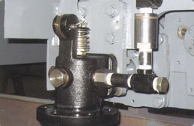
- An adjustable pressure control disc is mounted on the poppet valve to set the desired blowing pressure to each individual soot blower.
- A unique floating disc design allows for proper sealing of the steam or air during temperature change.
- Enclosed construction of the box beam provides maximum protection of all the working parts of the soot blower.
- Variable cross section wall thickness provides maximum strength of the lance tube during extension into the boiler.
- The “slipping rack design feature” provides a change in the cleaning position of the lance tube venturi nozzles each and every time the soot blower starts its forward travel.
- The expanda cable can be mounted externally for ease of maintenance.
Diagrams & Data
VS-C25/C45 soot blower is mainly made up of a traveling carriage, poppet valve, beam, wall box, power cable, front bracket, inner tub, lance, nozzle, electric box, limit switch control, helix phase change mechanism. The VS-C45 also has an intermediate lance and feed tube support assembly.
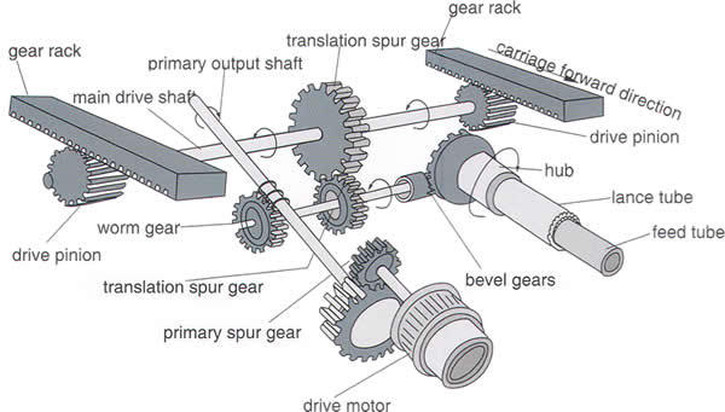
The drive train inside the traveling carriage consist of a worm and worm gear set. The worm gear is attached to the end of the main drive shaft. A translation spur gear is also attached to the main drive shaft and this spur gear is engaged with another spur gear located on the pinion shaft directly above. These two spur gears provide the forward and reverse travel of the soot blower. Also, on the main drive shaft are a small bevel which is engaged with a larger bevel gear mounted on the hub. These two bevel gears provide the rotation of the lance tube during traversing. Since there is only one set of bevel gears, the lance tube reverses its rotation of the lance tube in the opposite direction in the reverse travel. In other words, the lance tube rotates clockwise in the forward travel and counterclockwise in the reverse travel.
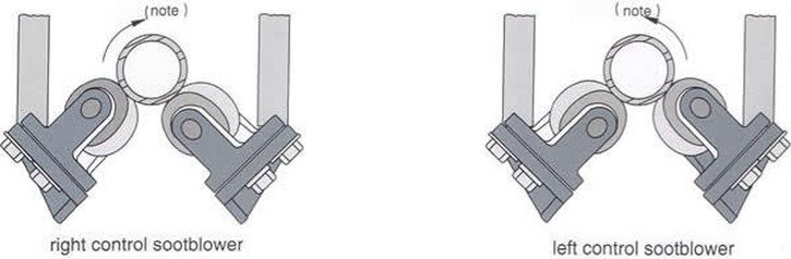
On the left sketch: RH soot blower carriage configuration. On the right side: LH soot blower carriage configuration.
The “slipping rack” design shown above provides loss motion of the traversing gearing momentarily, while the rotation of the lance tube does not. This design allows the venturi nozzles to be located in a different cleaning position each and every time the soot blower starts its forward travel. Over many different starts of operation the venturi nozzles will return to their initial starting position so that 360 degree cleaning is obtained.
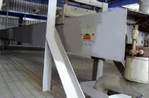
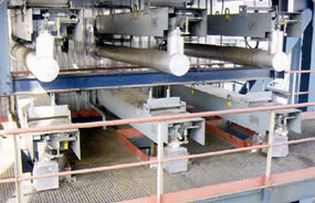
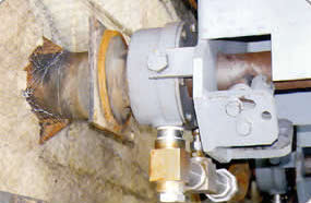
Installation Scene
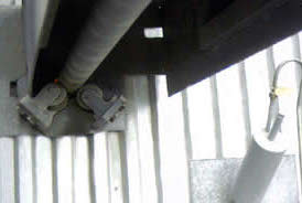
Soot Blower Carriage